Seismic restraint of non-structural elements in buildings
Introduction
During the recent Kaikoura and Canterbury earthquakes in New Zealand, it was observed that non-structural elements performed poorly, particularly in multi-storey buildings. The safety of building occupants can be put at risk due to non-structural elements falling on them. There are also significant disruption and economic losses due to poor seismic performance of non-structural elements.
Non-structural elements are not part of the primary and secondary structural systems of a building. Examples of non-structural elements include suspended ceilings, plant, ducting, pipework, cable trays and partitions. Together, they account for a significant proportion of the total building cost.
While the primary and secondary structural elements are generally well designed and detailed by a structural engineer as part of a building design, non-structural elements can be overlooked through the various stages of a project. From the recent Kaikoura and Canterbury earthquakes, it is clear that good seismic design of non-structural elements saves lives and costs.
Building Act 2004, Building Code and NZ Standards
The seismic design of non-structural elements is governed by the Building Act 2004, Building Code and various New Zealand standards such as NZS 4219: 2009 Seismic performance of engineering systems in buildings and NZS 1170.5: 2004 Part 5: Earthquake actions – New Zealand. The Building Code sets out the performance standards that all building work must meet. For seismic performance of non-structural elements, the relevant clause of the Building Code is B1 Structure, which requires all building elements to have a low probability of failure when subjected to earthquake loads during a building’s life.
To demonstrate compliance with the B1 requirement, a seismic engineer can use NZS 4219: 2009 to carry out both non-specific and specific seismic restraint design for a variety of non-structural elements. However, some elements are excluded from NZS 4219: 2009, for example, suspended ceilings and internal partitions. If an element is not covered by NZS 4219: 2009, the seismic engineer can use NZS 3404: 1997 Steel structures standard and AS/NZS 2785: 2000 Suspended ceilings – Design and installation together with NZS 1170.5: 2004 to deliver a compliant design.
Design Procedure
According to NZS 4219: 2009, non-structural elements should be designed, constructed and installed within a building to resist earthquake loads, reduce life and injury hazards and protect property and systems from damage or the loss of function. Based on the expected performance under an earthquake, non-structural elements can be classified into 7 categories: P1 – 7. There are 5 building importance levels: IL1 – 5 (Standards New Zealand, 2009; Standards New Zealand, 2004).

Seismic restraint of pipework in Auckland - our recent work

Seismic restraint of heavy equipment in Christchurch - our recent work
For seismic design of non-structural elements such as a pipe or cable tray, a seismic engineer first chooses a building importance level and a component category. Then, the static earthquake load is calculated. The earthquake load demand is equal to the seismic coefficient multiplied by the operating weight of the component. The seismic coefficient is based on several other factors including the earthquake zone factor, component’s height factor, component performance factor and component risk factor. The earthquake zone factor represents the relative level of seismicity for cities and towns in New Zealand. The component performance and risk factors are determined based on the building importance level and component category. The component height factor significantly increases the earthquake load demand for components above the ground floor (Standards New Zealand, 2009; Standards New Zealand, 2004).
From the calculated earthquake load demand, the seismic engineer then determines the axial force acting on the brace. This calculation depends upon the component type: a linear, floor-mounted or suspended component. Then, the brace and fixings are designed to meet the calculated brace force. Non-specific design of braces includes steel angles, flats, square hollow sections and threaded rods. Non-specific design of fixings covers woodscrews, coach screws, bolts and cast-in anchors. There are also many proprietary systems available on the market, including braces and fixings, which are extensively tested to determine reliable capacities (Standards New Zealand, 2009; Standards New Zealand, 2004).
If a component is connected to more than one floor, it must be designed to accommodate the relative seismic displacement between floors. This displacement can be obtained from the structural engineer responsible for the design of the primary and secondary structural systems of the building. NZS 4219: 2009 allows the use of flexible joints to sustain the relative displacement between connection points (Standards New Zealand, 2009).
Building Services
Mechanical, electrical and hydraulic engineering systems used in a building may include pipework, ducting, cable trays, cabinets and equipment. These components should be seismically restrained to NZS 4219: 2009. However, there are some exceptions (Standards New Zealand, 2009).

Equipment restraint options
NZS 4219: 2009 states that piping systems must be seismically restrained except for pipes with a diameter less than 50mm or with individual hangers less than 150mm long from the top of the pipe to the supporting structure. A pipe is required to be restrained at the points of: connection of branch pipes, connections to equipment, on at least one side of flexible couplings and where the free swaying of the pipe may damage other building components (Standards New Zealand, 2009).
Each straight portion of a horizontal pipe should have at least two transverse restraints and at least one longitudinal restraint. Each straight segment of a vertical pipe should have at least two transverse restraints in each orthogonal direction. The restraints should be installed on the vertical pipe within two pipe diameters of a vertical support and perpendicular to the pipe axis, with the restraint centreline as closely as practical intersecting with the pipe axis (Standards New Zealand, 2009).

Example of transverse pipe restraint
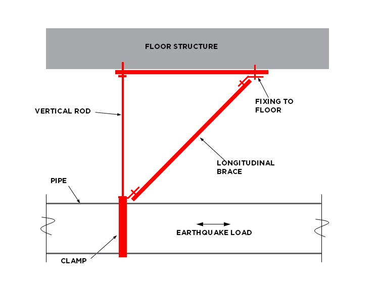
Example of longitudinal pipe restraint
All ducting systems must be seismically restrained. There are two exceptions. The first one is a rigid ductwork supported by hangers that are less than 200mm long from the duct support position to the structural support. The second exception is a flexible ducting system with a length less than 1.5m. Seismic restraints must be able to prevent movements in all directions. Suspended elements that are installed in line with the duct system and have an operating weight greater than 10kg, such as fans, heat exchangers and humidifiers, should be supported and laterally braced independently of the duct system (Standards New Zealand, 2009).

Example of transverse duct restraint

Example of longitudinal duct restraint
All electrical components within a cabinet should be positively restrained using straps, bars, bolts and similar devices. Cabinets should have hinged or sliding doors fitted with top and bottom catches. Freestanding cabinets should be restrained to the building structure. All cable tray systems must also be restrained for earthquake loads unless they are used to support non-essential electrical services, or they are suspended less than 400mm below the structural support (Standards New Zealand, 2009).
Suspended Ceilings
Suspended ceilings are excluded from the scope of NZS 4219: 2009. Instead, suspended ceilings should be designed to resist earthquake loads in accordance with NZS 1170.5: 2004 and AS/NZS 2785: 2000. AS/NZS 2785: 2000 also allows both non-specific and specific seismic design of suspended ceilings. Non-specific design is based on guidance provided by ceiling manufacturers and typically involves a prescriptive solution to provide seismic restraint to the type of ceiling being considered. In many cases, a specific ceiling design is required for reasons such as complexity and size of the ceiling, floor to ceiling height and building importance level. Both non-specific and specific designs must be able to accommodate earthquake loads derived in accordance with NZS 1170.5: 2004 (Standards Australia/Standards New Zealand, 2000; Standards New Zealand, 2004).
There are two common types of seismic restraint systems for suspended ceilings. The first one is known as perimeter-fixed ceilings, which are vertically supported using wires or cable hangers and laterally restrained by fixing two edges of the ceiling (in two orthogonal directions) to a wall or frame. The other two edges are typically free to move against the wall or frame with sliding connections. If the perimeter fixing does not provide enough bracing capacity, then the other option is a floating ceiling, which is braced to the underside of the floor structure above to provide lateral resistance. The ceiling edges are not fixed to the wall or frame. There needs to be a sufficiently large gap between the ceiling and the adjacent wall or frame to ensure that the ceiling is not damaged against the wall or frame during an earthquake. The lateral bracing to the floor structure above may include rigid braces or cable or wire braces together with vertical struts.

Typical perimeter-fixed suspended ceiling

Example of bulkhead restraint
Internal Partitions
In a building, there are load-bearing and non-load-bearing walls. Non-load-bearing walls are also known as partitions. Partitions are also not covered by NZS 4219: 2009. Partitions are typically timber or cold-formed steel framed walls lined with plasterboards on both sides. While they do not support gravity loads, an earthquake load can be generated from their own weight. Cold-formed steel framing is much lighter than timber and thus attract less earthquake loads. Partitions should be seismically restrained. The most common way is to brace the top of the wall to the underside of the floor structure above. The floor structure should be designed adequately to provide lateral support to partitions and other non-structural elements such as building services. The braces at the wall top are typically rigid braces as shown below.

Example of internal partition restraint
How Can We Help You?
As seismic engineering specialists, we work with building services engineers and contractors, architects, manufacturers, suppliers, and building owners to design and implement seismic restraint systems for non-structural elements including mechanical and electrical plant, ducting, pipework, tanks, cable trays, lighting, suspended ceilings, partition walls, cladding systems, and much more. We provide the following:
Seismic restraint layout markup drawings.
Seismic restraint design details.
Technical specifications.
Structural calculations.
A design producer statement (PS1) confirming that the design meets the Building Code. Where the design and documentation are prepared by others for review and certification, we provide a design review producer statement (PS2).
A construction review producer statement (PS4) confirming that the works have been completed in accordance with the design requirements.
References
Standards New Zealand, (2009). NZS 4219: Seismic Performance of Engineering Systems in Buildings.
Standards New Zealand, (2004). NZS 1170.5: Structural Design Actions Part 5: Earthquake Actions – New Zealand.
Standards Australia/Standards New Zealand, (2000). AS/NZS 2785: Suspended Ceilings – Design and Installation.